TY-LS-214 Tracking Laser Seeke
FUNCTION
A. It has a self-check function;
B. It can be powered on and bind the laser code according to the instructions of the rocket navigation and guidance device;
C. It can preset the frame angle according to the instructions of the rocket navigation and guidance device (before capturing the target, and after entering the memory tracking and memory timeout states);
D. It can automatically capture and track the target;
E. It can recapture and track the target after losing the target, and output the guidance information normally;
F. It can output the guidance information such as the line of sight angular velocity and frame angle signal to the rocket navigation and guidance device;
G. It can safely and reliably provide the shield ejection signal output by the navigation and guidance device to the nose cone assembly;
H. It has the function of a hit-off switch, and provides a dual-path hit off signal to the fuze at the moment the seeker touches the ground. The hit-off switch is required to be safe and reliable;
I. It can send the line of sight angular velocity, frame angle signal, received laser energy intensity, seeker status information, current laser code, seeker gain control status information, software version number, product batch number, manufacturer code and other information to the telemetry device;
J. It should have an anti-collision frame function. k) It is possible to achieve multiple rockets attacking multiple targets simultaneously (targets are illuminated using different codes);
K. Definition of frame angle and line of sight angular velocity polarity
L. Looking back from the seeker (assuming the current frame angle is 0), when the target is on the left side of the seeker center axis, the frame moves, outputs the positive yaw frame angle and yaw line of sight angular velocity; when the target is on the upper side of the seeker center axis, the frame moves, outputs the positive pitch frame angle and pitch line of sight angular velocity;
PERFORMANCE INDICATORS
A. Working wavelength: 1.064um;
B. Maximum operating distance: greater than or equal to 7km (visibility is not less than 10km, illuminator output energy is not less than 80mJ, irradiation distance is 5km, target diffuse reflection coefficient is 0.2);
C. Blind area: less than or equal to 50m (visibility is not less than 10km, illuminator output energy is not less than 80mJ, irradiation distance is 500m, target diffuse reflection coefficient is 0.2);
D. Instantaneous field of view: not less than ±7°;
E. Frame angle range of tracking target
Yaw: -17.5°~+17.5°
Pitch: -17.5°~+17.5°
F. Frame angle output error: absolute error is not greater than 0.3°;
G. Maximum tracking line of sight angular velocity: not less than 3.5°/s;
H. Steady-state tracking angular velocity error
1) When the line of sight angular velocity is greater than 1.5°/s When the line of sight angular velocity (mean) absolute error is less than or equal to 10%;
2) When the line of sight angular velocity is less than or equal to 1.5°/s , the absolute error of the line of sight angular velocity (mean) is less than or equal to 0.15°/s;
3) The peak-to-peak value of the noise band is less than or equal to 0.2°/s (2σ, indoor equivalent 4Km receiving energy);
I. Isolation: less than or equal to 3% (5°/1Hz sine swing, 3°/2Hz sine swing);
J. Target capture time: The seeker should be able to correctly capture the target within no more than 5 effective photoelectric pulses;
K. Capture to tracking time: When the target is located at a 12° field of view, the time from capturing the target to tracking the target should not exceed 1.7s;
L. Power-on self-test time: no more than 15s;
M. Working voltage range: 24V~32V;
N. Steady-state working current: no more than 1.6A (under 28V working voltage);
O. Peak current after stable operation after power-on: no more than 4A;
P. Single continuous working time: no less than 60min;
Q. Laser coding
1) Coding type: fixed frequency coding and hopping frequency coding. 2) Number of coding groups: 8 fixed frequency coding groups, no less than 8 hopping frequency coding groups, and the hopping frequency coding length is 1024 hoppings;
3) Usage mode: There are two modes of laser coding setting and adaptive mode. In the setting mode, the fixed frequency coding and hopping frequency coding can be manually selected; in the adaptive mode, the fixed frequency coding and hopping frequency coding can be automatically identified;
4) Expansion interface: It has an interface for adding new laser coding; it has the ability to update the original laser coding.
R. Anti-sunlight interference ability: It can work normally when the angle between the optical axis and the sun is greater than 15 degrees;
S.Break switch: Normally closed, the normally closed resistance is not greater than 10Ω; the insulation resistance with the shell is not less than 50MΩ at normal temperature. The insulation resistance between the nose cone component throwing cover circuit and the shell is not less than 50MΩ at normal temperature.
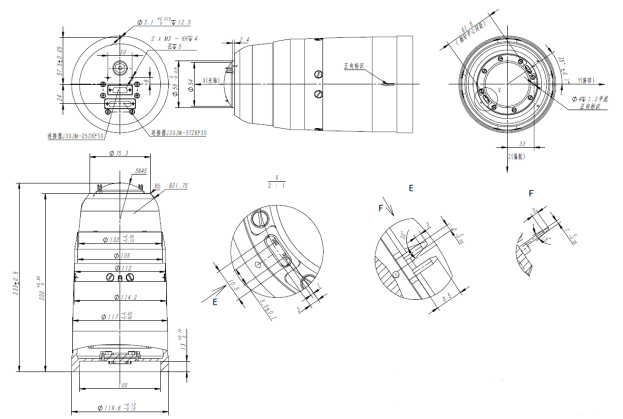
MECHANICAL DIMENSION(mm)